Hello Guest! Welcome to our store!

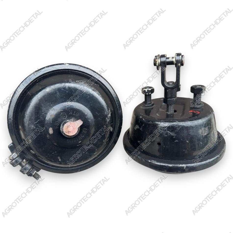
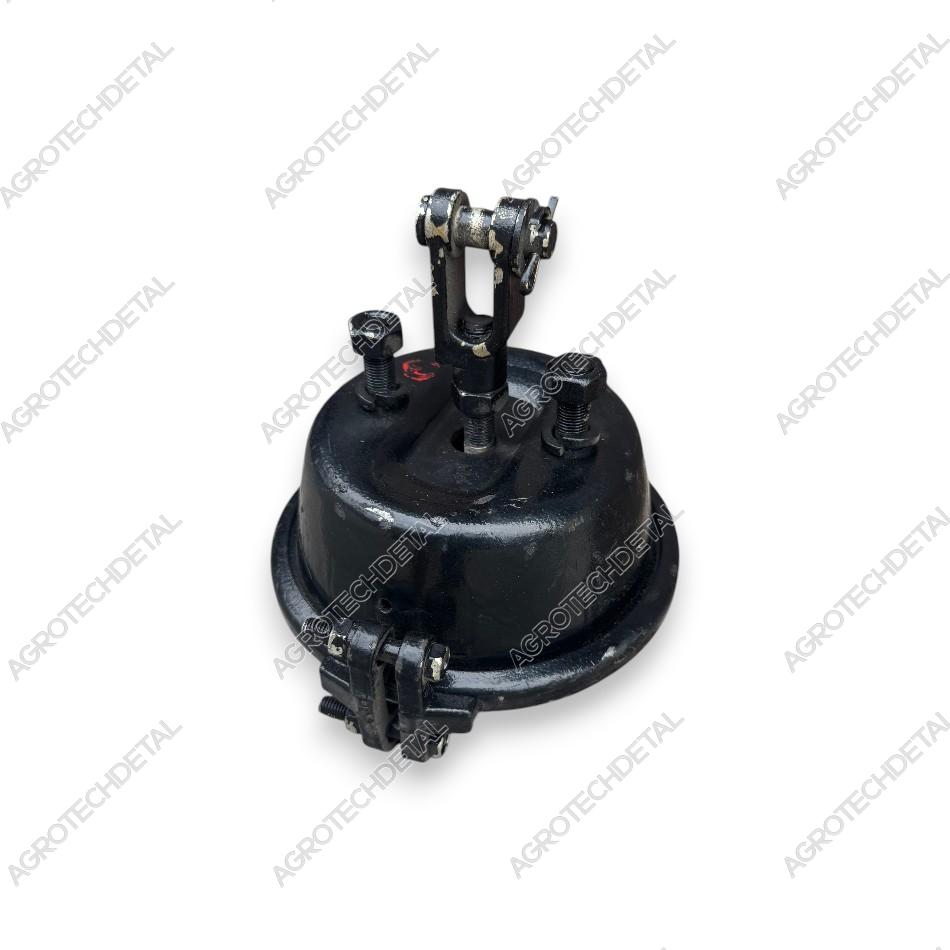
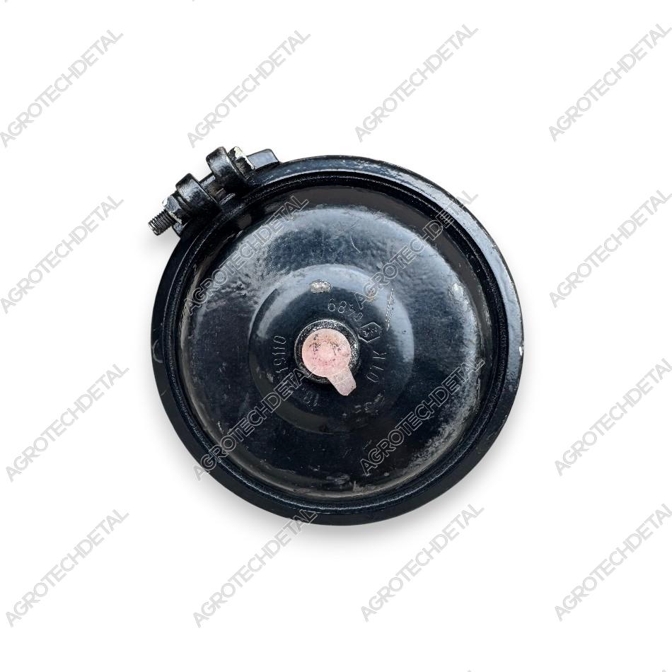
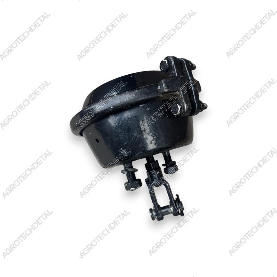
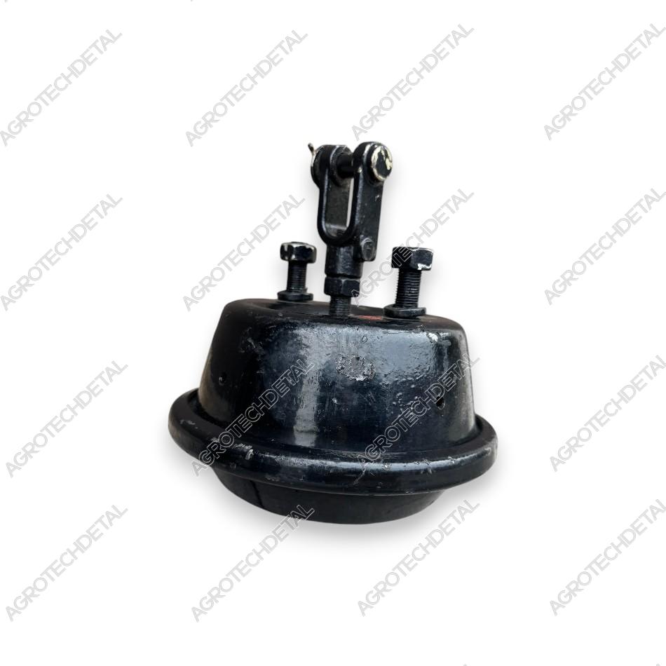


Brake Chamber 500-3519010-01 is used in the pneumatic system of HTZ tractors and is designed to convert compressed air pressure into mechanical force required to operate the brake mechanisms and the clutch control system.
On HTZ wheeled tractors, four brake chambers are installed as part of the wheel braking system. In addition, one 500-3519010-01 Brake Chamber is used in the main clutch control mechanism on both wheeled and crawler HTZ tractors.
The chamber is connected using the following components: Brake Hose 200-3506060-B1, Elbow Fitting 151.64.221, and Tube Nipple 125.64.284. The main serviceable component is the Diaphragm 100-3519150 / 500-3519050, which can be replaced separately without purchasing a complete brake chamber.
The original Soviet-manufactured brake chamber is distinguished by its high manufacturing quality, durable steel housing, and long service life, ensuring reliable operation of the pneumatic system even under demanding working conditions.
The brake chamber is used on HTZ T-150K, T-151K, T-156, HTZ-17221 wheeled tractors, as well as on HTZ T-150G crawler tractors in the main clutch control assembly.
In this section, you'll find an assembly drawing with the location of all parts and their catalog. This will help you identify the required part, find its catalog number, check the completeness of the unit, and select parts for replacement or repair.
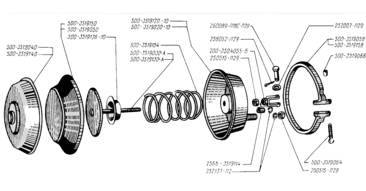
Bolt М16х2 202119-П29, Bolt М8х55 500-3519064, Fork 200-3504055-Б, Nut 2М12х1,25.5.019 250515-П29, Nut 500-3519066, Diaragma 500-3519050 / 500-3519150, Rear / front brake chamber assembly 500-3519110-02, Housing 500-3519020-10, Left bracket 256Б-3519071, Right bracket 256Б-3519070, Cover 500-3519040 / 500-3519140, Pin 260089-P29, Adapter 256B-35191114, Spring 500-35119154, Cup. Thrust 500-3519136-10, Clamp 500-3519058, Brake cylinder assembly 214-3519110-B, Washer 12 252007-P29, Spring washer 12 252137-P2, Spring washer 16 252139-P2, Cotter pin 3.6x20 258052-P29, Brake chamber rod 500-3519030-A, Rod 500-3519130-A.
Video review of brake camera 500-3519010-01. Watch the video
to familiarize yourself with this spare part in more detail before purchasing.
